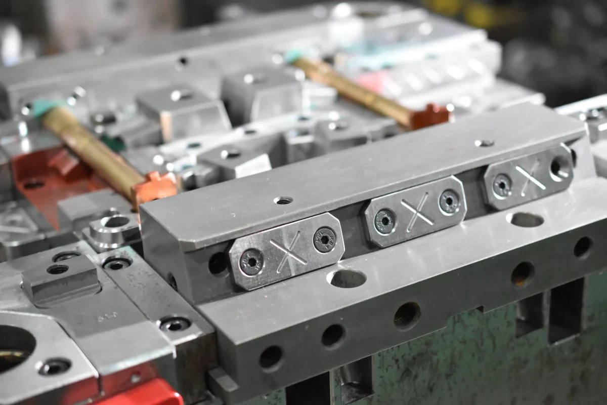
Custom mold solutions make the most sense when part geometry, production volume, material behavior, tolerance, cycle time, and maintenance need to be designed together. A mold producing 500,000 parts per year can turn a 3-second cycle difference into more than 400 machine hours across several years of production. Cooling can account for roughly 50–80% of an injection molding cycle, while a poorly placed gate or uneven wall thickness can increase warpage, sink marks, weld lines, and dimensional variation. A custom mold gives engineers more control over repeatability, tooling life, scrap, automation, and cost per finished part instead of focusing only on the initial mold price.
A production mold should be designed from the expected manufacturing conditions rather than from the CAD shape alone. Engineers normally review resin type, projected annual volume, part dimensions, wall thickness, cosmetic surfaces, tolerance zones, molding-machine capacity, expected cycle time, assembly interfaces, and planned automation before finalizing the tool layout. A program targeting 1 million parts over five years has different requirements from a project producing 10,000 service components, even when both parts have similar dimensions.
That volume difference affects mold steel, number of cavities, runner design, cooling layout, wear allowances, spare components, and maintenance planning. A low-volume aluminum or pre-hardened tool may be commercially sensible for several thousand parts, while higher-volume programs often justify more wear-resistant steels and replaceable inserts. Glass-filled materials increase abrasive wear at gates, ribs, shutoffs, cores, and cavity surfaces, so tooling choices should reflect the resin rather than relying on one material specification for the full mold.
The next consideration is part geometry because mold cost rises quickly when a design requires slides, lifters, unscrewing systems, collapsible cores, or several independent moving components. A simple open-and-close mold may contain only a small number of major moving elements, while a part with four side undercuts may require four slide assemblies plus additional locking, guiding, lubrication, and wear components. Each mechanism creates another location that must remain aligned through tens or hundreds of thousands of cycles.
For that reason, DFM work is normally completed before steel machining starts. Engineers review draft, ribs, bosses, holes, wall transitions, undercuts, shutoff angles, ejector locations, gate appearance, and likely shrinkage. Many molded thermoplastics require around 0.5–2° of draft on ordinary surfaces, while deeper texture often needs more. A 0.5 mm wall-thickness difference near a cosmetic surface can also change local cooling and shrinkage enough to create visible sink or distortion.
Changing a CAD feature before machining may require hours. Changing the same feature after a hardened cavity has been cut may require welding, machining, polishing, another mold trial, dimensional inspection, and several days of lost schedule.
Wall thickness also connects directly to filling pressure and cooling time. Thin sections require the melt to travel through narrower flow paths before the polymer freezes, while thick areas retain heat longer and can shrink more during cooling. A 1.5 mm nominal wall with a sudden 4 mm boss base creates a different cooling condition from a properly cored boss with a thinner connection to the main wall. The mold therefore needs geometry, gate location, cooling, and process settings that work as one system.
Cooling deserves particular attention because it often occupies 50–80% of the total injection molding cycle, depending on resin, thickness, mold temperature, and part geometry. If one area needs 18 seconds to reach safe ejection temperature while most of the part needs only 10 seconds, the machine still has to wait for the slow region. Across 2 million cycles, an 8-second difference represents more than 4,400 machine hours.
| Design area | What engineers normally evaluate | Production effect |
|---|---|---|
| Cooling | Channel location, diameter, flow rate, hot areas | Cycle time, warpage, dimensional consistency |
| Gating | Gate type, location, number, vestige | Filling balance, weld lines, pressure |
| Venting | End-of-fill areas, rib ends, deep pockets | Burns, short shots, trapped gas |
| Ejection | Pin area, sleeve location, stripper design | Part marks, sticking, deformation |
| Cavitation | Clamp force, shot size, balance | Output per cycle, mold size, cost |
Cooling layout then influences how many cavities can be run reliably. A four-cavity mold can theoretically produce four times as many parts per cycle as a single-cavity mold, but only when all four cavities fill, pack, cool, and eject within an acceptable process window. If one cavity runs hotter or fills later, operators may have to increase cycle time or widen process settings just to keep every cavity acceptable.
Runner selection follows the same production logic. A cold runner is usually simpler and less expensive to build and maintain, but every cycle can produce runner material in addition to saleable components. Suppose four molded parts weigh 20 g each and the cold runner weighs 15 g. Material entering the mold is 95 g per shot, so around 15.8% of that shot is runner material before regrinding or disposal is considered.
A hot runner can reduce that runner mass, although it adds heaters, thermocouples, manifolds, nozzles, controllers, seals, and more maintenance points. If a resin costs $4 per kilogram and a cold runner produces 15 g of non-product material over 500,000 cycles, the gross material represented by the runner reaches 7,500 kg, or $30,000 before any approved regrind is deducted. That comparison is more useful than saying one runner system is always better.
Mold-flow simulation can support the gating and runner work by estimating filling sequence, pressure, weld-line positions, air traps, temperature distribution, packing behavior, and possible warpage. Simulation does not replace molding trials because the model depends on material data, process assumptions, machine behavior, and actual tooling conditions, but it allows engineers to compare several layouts before machining. Testing three gate locations digitally is cheaper than machining three different gate systems into completed steel.
Trial results then provide the physical data needed for refinement. A first tool trial may include 20, 50, or more parts once stable processing conditions are reached, followed by dimensional measurement, visual inspection, assembly checks, weight comparison, and process recording. For precision parts, several samples from each cavity may be measured separately because a four-cavity tool can show cavity-to-cavity differences even when the parts look identical.
Dimensional control needs particular attention when molded components interface with seals, bearings, electrical connectors, clips, or metal inserts. Polymer shrinkage is not one fixed percentage across every direction and feature. Many unfilled thermoplastics shrink roughly around 0.5–2%, while semicrystalline and reinforced materials can behave very differently depending on fiber orientation, packing pressure, wall thickness, and mold temperature. Tool dimensions therefore need compensation based on the actual resin and geometry.
A supplier such as Qlution Manufacturing can be evaluated on how it handles that engineering work before production, including mold design review, material compatibility, machining capability, trial procedures, dimensional inspection, modification control, and support after the tool enters service. Buyers should ask for measurable information rather than general capability statements: machining tolerance, inspection equipment, planned steel grade, expected mold life, cavity count, runner type, spare-part plan, and trial criteria.
Maintenance planning should be included at the same stage because production molds operate as mechanical systems. Slides, lifters, ejector pins, leader pins, bushings, springs, seals, hot-runner components, and shutoff surfaces wear at different rates. A mold scheduled for 1 million cycles may justify replaceable gate inserts and wear plates so damaged areas can be serviced without rebuilding a full cavity block.
Production teams can also establish preventive-maintenance intervals based on actual molding conditions. A tool running a clean unfilled resin may need less frequent attention than one processing 30% glass-filled material, flame-retardant resin, or a material that leaves deposits in vents. Checking vents every 25,000 cycles may be reasonable for one process, while another program may require cleaning after 5,000–10,000 cycles because residue appears sooner.
Ejection reliability becomes more important as maintenance intervals grow. Ejector pins must push on areas strong enough to resist local deformation, and deep ribs or textured walls may hold the part tightly around the core. If a part requires 12 ejector pins but only six are used to save tool cost, the resulting force may be concentrated enough to leave visible marks or distort the component after several seconds of hot ejection.
Automation adds another layer because robot access, gripper clearance, part orientation, insert placement, mold-open distance, and cycle timing all need to be planned before the tool is finished. Removing 5 seconds of manual handling from a 30-second cycle represents a 16.7% reduction in elapsed cycle activity when the robot can perform the task inside the existing machine sequence. Across 750,000 parts, even small reductions can affect labor and machine availability.
Surface finish also changes tooling requirements. A polished visible housing, a textured automotive interior part, and a functional industrial enclosure should not use identical assumptions for draft and gate position. Texture depth can increase the draft needed for release, while a high-gloss surface can make weld lines, gate blush, flow marks, or polishing differences easier to see. Cosmetic requirements should therefore appear in the mold specification before polishing starts.
Cost comparisons become more accurate when buyers separate tooling price from part cost. Assume Mold A costs $35,000 and Mold B costs $48,000, creating a $13,000 difference. If Mold B saves only $0.015 per molded part through lower scrap, shorter cycle time, or lower material use, the additional tooling cost is recovered after about 867,000 parts. A five-year program producing 400,000 parts annually would exceed that volume during the third production year.
Scrap percentage has a similar effect. Reducing reject rate from 3% to 1% on an order requiring 1 million accepted parts removes roughly 20,000 rejected units per million attempted good parts, with the exact production quantity depending on yield calculations. When the component uses expensive engineering resin or requires secondary machining, painting, printing, assembly, or inspection, the cost attached to those rejected units can exceed the raw molded-part cost.
Supplier selection should therefore include technical communication as well as machining capacity. A mold maker should be able to explain why a gate was placed on one surface, why a specific steel was chosen, how cooling reaches a deep core, where wear inserts are located, and how the tool will be serviced after 100,000 or 500,000 cycles. Answers supported by drawings, dimensions, material specifications, inspection reports, and trial records are more useful than marketing claims.
Before approving the tool, the buyer can request a defined validation package rather than relying on a small set of attractive samples. Depending on the product, that package may include cavity-specific dimensional reports, resin and steel records, process settings, sample quantities, mold photographs, spare-component lists, cooling diagrams, maintenance instructions, and trial data. A 30-part inspection set from a six-cavity mold, for example, gives five measured samples per cavity instead of mixing every cavity into one average.
Long-term production then depends on repeatability rather than the quality of one trial shot. A mold that produces acceptable samples at one narrow pressure and temperature setting may be difficult to operate across normal shop conditions. A better production tool gives technicians enough processing range to manage ordinary material, ambient, and machine variation while holding dimensions and appearance within specification.
For manufacturing programs measured in hundreds of thousands of parts, the stronger custom mold is usually the one that connects geometry, resin, cooling, gating, ejection, tool materials, maintenance, inspection, and automation to the same production target. The purchase price is paid once; cycle time, scrap, material use, downtime, and maintenance are paid repeatedly over every production year.